
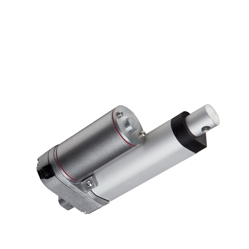
LA10H with hall sensor
150mm/s,900N/90KG/198LBS load,hall sensor position feedback,customized
150mm/s,900N/90KG/198LBS load,hall sensor position feedback,customized
Advantage
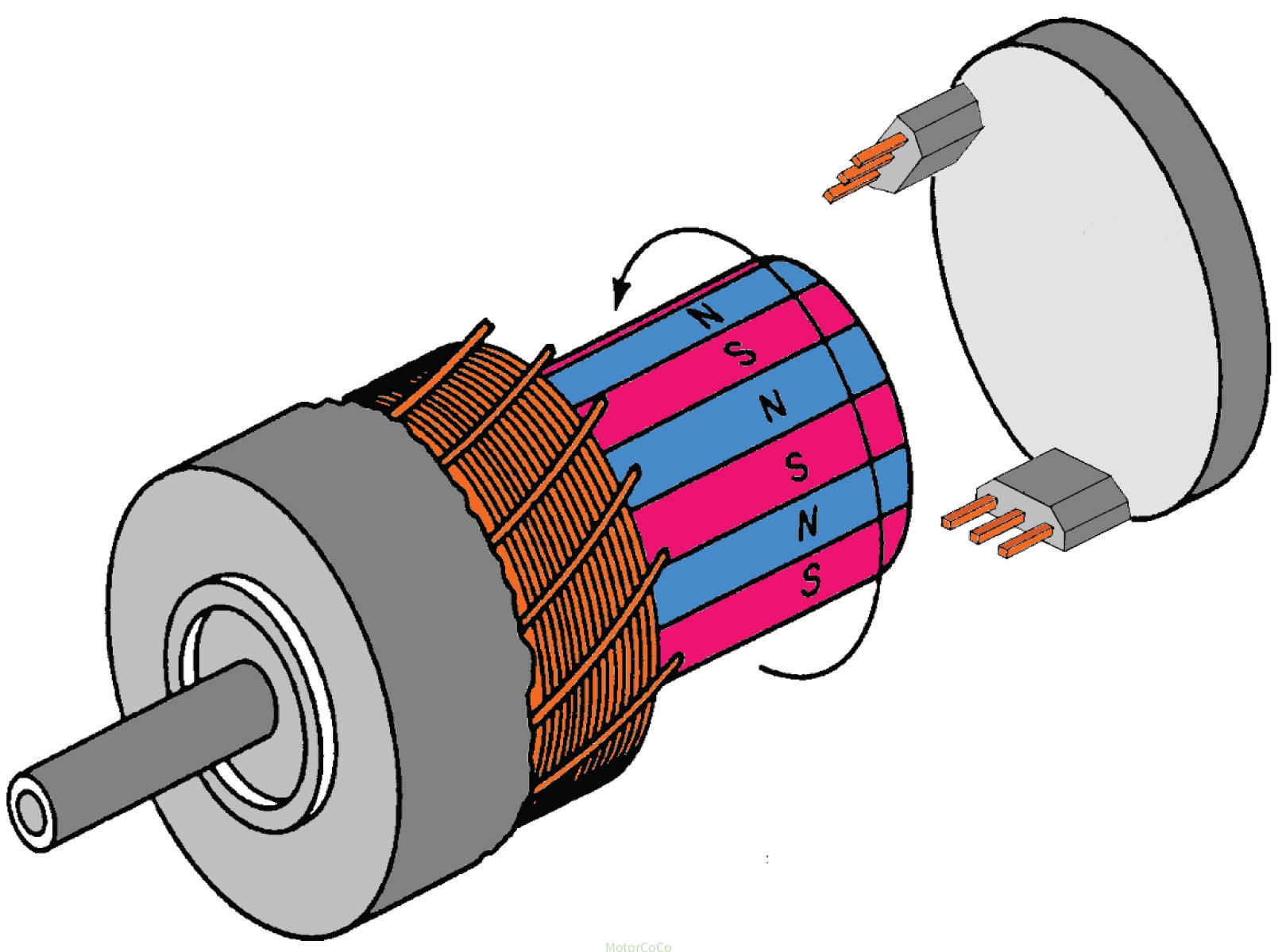
Magnetized Disk: Inside the motor gearbox, there's a shaft with a magnetized disk attached to it. This disk has alternating North and South poles around its circumference.
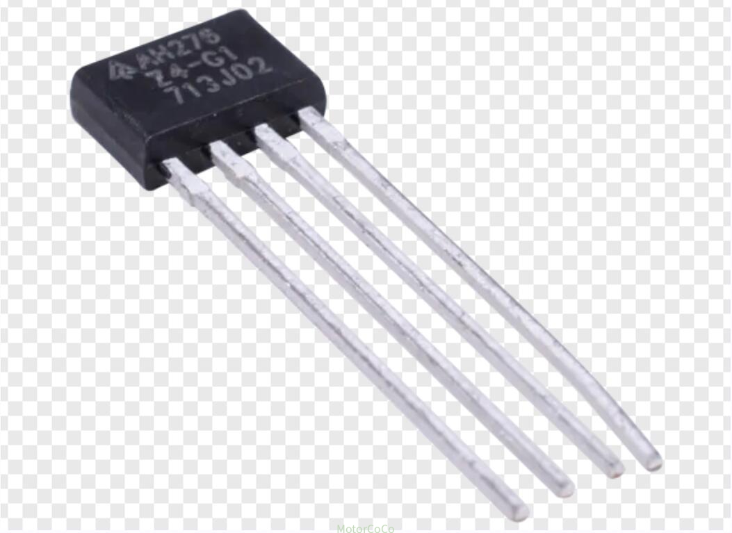
Hall Sensor Array: Positioned nearby, likely along the path of the disk's rotation,there's an array of Hall sensors. These sensors detect changes in the magnetic field as the poles of the disk pass by.
Pulse Output: Similar to before, each transition from a North pole to a South pole (or vice versa) induces a change in pulse in the Hall sensors.
Counting Poles: By counting these pulse transitions, the controller system can determine the position of the linear actuator. Each complete revolution of the magnetized disk corresponds to a certain linear displacement of the actuator. By measuring the number of revolutions and possibly considering the gear ratio, the linear position can be accurately calculated.
Main technical data
| Model | LA10H |
| Input | 12V,24V,36V,48V DC |
| Load/Force/Thrust | Max 900N/90KG/198LBS,customized |
| Speed | Max 150mm/s,6inch/s,customized |
| Stroke | Max 1000mm,40inch,customized |
| Limited switch | Build in,customized |
| Position signal feedback | Hall sensor |
| Gear material | Metal |
| Duty cycle | 25% |
| IP protection | IP54,IP65 or customized |
| Operation Temperature | -25°C to 65°C (-13°F to 149°F) |
| Color | Black or Silver |
| Controller | Power supply,wire or wireless switch,synchronous controller options |
| Mounting bracket | Standard type or customized |
| Certificate | CE,Rohs,ISO,UL |
Gear Ration&Load&Speed&Current
| Gear Ration | Max Force/Load N | Noload speed MM/S | 12V max current A | 24V max current A | Customized |
| A | 900N/90KG/198LBS | 6 | 4.2 | 2.1 | Yes |
| B | 750N/75KG/165LBS | 10 | 4.2 | 2 | Yes |
| C | 600N/60KG/132LBS | 15 | 4.2 | 2 | Yes |
| D | 450N/45KG/99LBS | 20 | 4.2 | 2 | Yes |
| E | 350N/35KG/77LBS | 25 | 4.1 | 2 | Yes |
| F | 300N/30KG/66LBS | 30 | 4.2 | 2.1 | Yes |
| G | 120N/12KG/26.4LBS | 40 | 4 | 1.9 | Yes |
| H | 100N/10KG/22LBS | 50 | 4 | 1.9 | Yes |
| I | 80N/8KG/17.6LBS | 60 | 4 | 1.9 | Yes |
| J | 50N/5KG/11LBS | 80 | 4 | 1.9 | Yes |
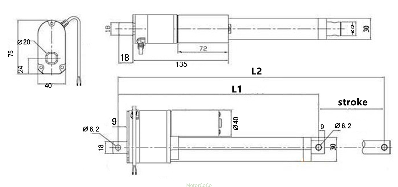
Drawing
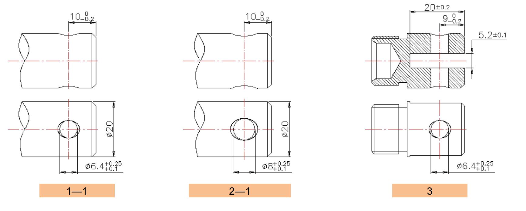
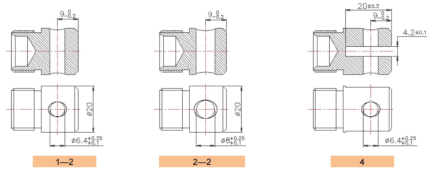
Head and tail connector options
FAQ
Lmin means when the linear actuator completely retracts,the length between the front hole and rear hole.
Lmin=140mm/5.6inch+Stroke. For example 50mm stroke,Lmin=140+50=190mm=7.6inch
Lmax means when the linear actuator completely extends,the length between the front hole and rear hole.
Lmax=Lmin+Stroke For example 50mm stroke,Lmax=190+50=240mm=9.6inch
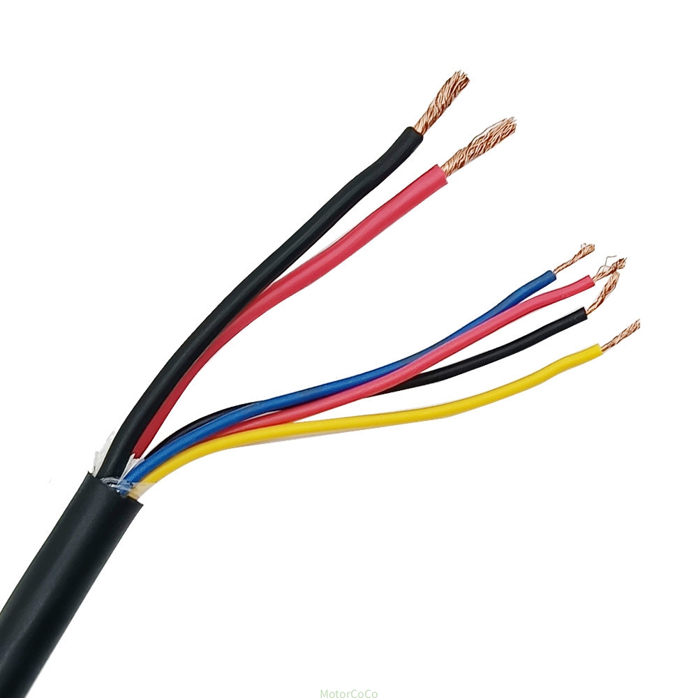
Wire diagram
There is 5 pcs cable. Red cable is + and black cable is -. If the power+ connects red cable +,power- connects black cable-,the linear actuator will extend,If the power+ connects black cable -,power- connects red cable +,the linear actuator will retract.
If customers want customized front and rear mounting hole size,Lmin and Lmax size,mounting degree or direction,please send technical data.
General question
1 Can you make customized stroke,Lmin,Lmax length? Yes,but we need drawing.
2 Can you make head connector with customized slot or fish eyes? Yes,but we need drawing.
3 Can you adjust end rear with 90 degree? Yes.
4 Can you make customzied cable connector? Yes,but we need connector photo or size.
5 Can you provide power supply or adapter or remote controller or syncrounously controller? Yes,we have wire and wireless types controller.
6 Can you provide mounting bracket? Yes.
7 Can you offer OEM serive?Yes.
How to place customized order
A Product model Number (For example LA10H,LA50H,LA51H or other model)
B Input (6V or 12V or 24V or 36V or 48V)
C Noload speed (For example 5mm/s or 10mm/s or 20mm/s or other speed)
D Load (For example 500N/50KG/110LBS or 700N/70KG/154LBS or other load)
E Stroke length (For example 2inch,50mm,4inch,100mm or other length)
F Retract length (For example 155mm or 205mm or other length)
G Cable length (For example 1M or 1.5M or other length)
H Other customized technical requirements